 |
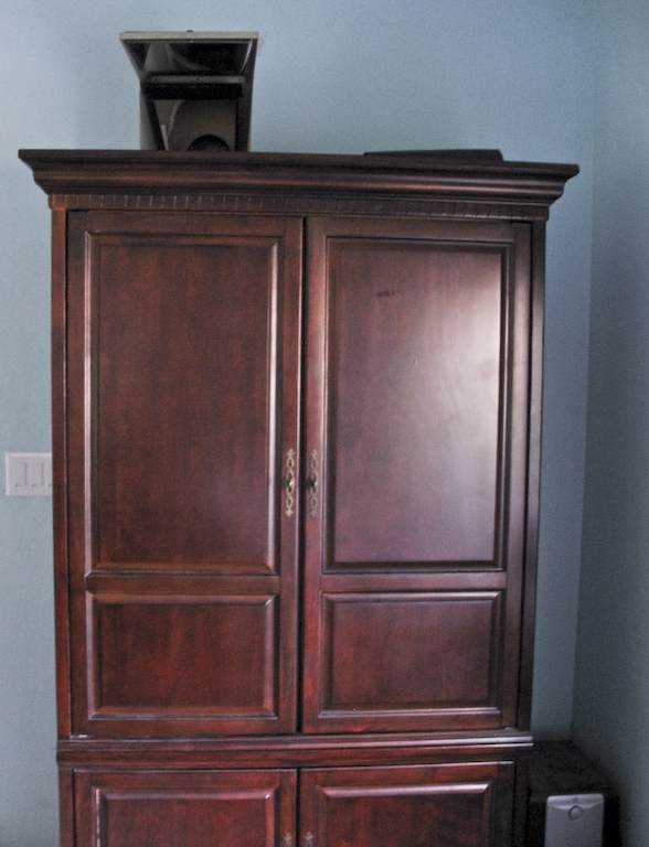
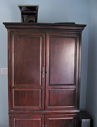
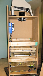
Here's the projector tucked away inside a TV console with a front-surface mirror to bounce the image to the screen on the wall. |
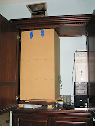 |
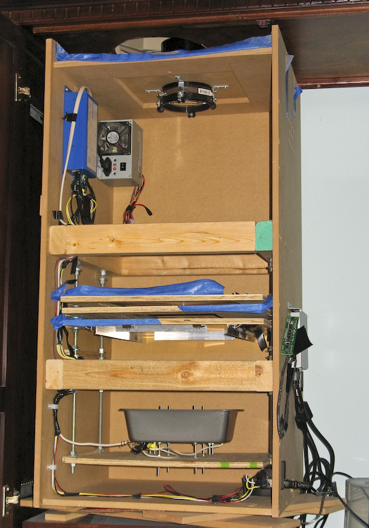
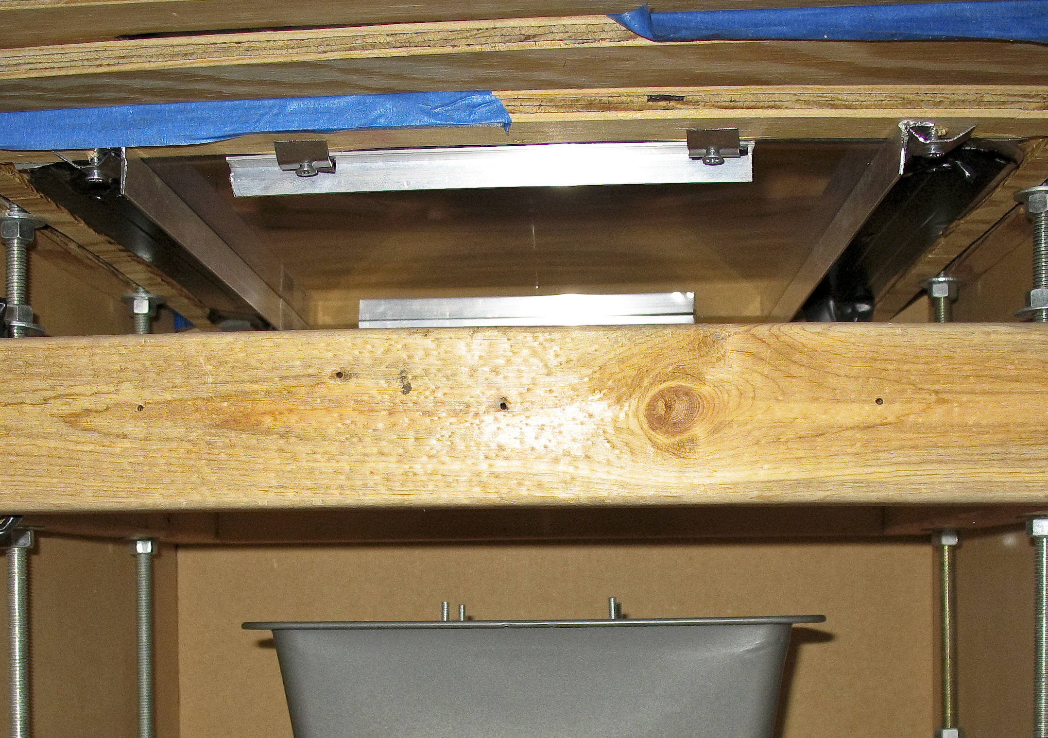
Inside the TV console. The projector is on "temporary" stilts of 2x3s and shelves until I build a base of the appropriate height. The console is about 2 inches too shallow for the projector, so the back panel has been removed. |
 |
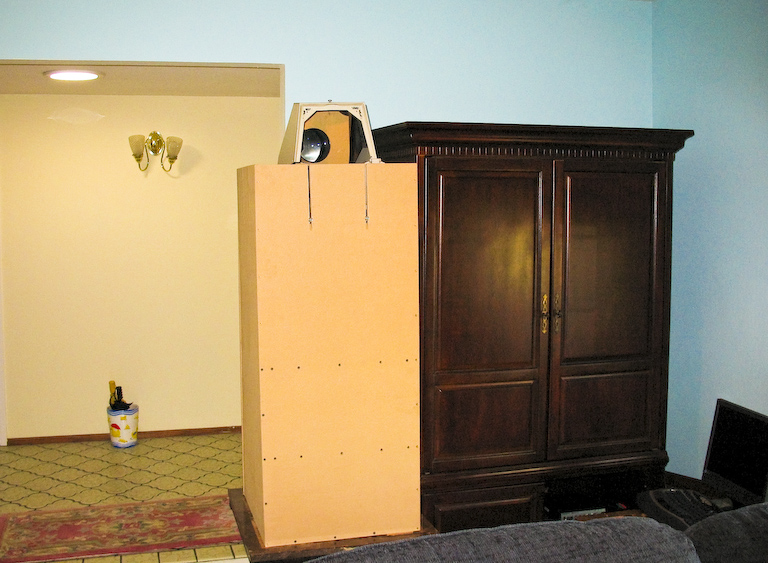
For a couple months I hadn't cut the hole in the top of the TV console, so it rested to the side on an end table |
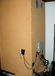 |
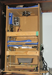
The back side. The LCD controller board is screwed directly into the MDF with short wood screws and covered up with a plate. The buttons and IR reciever for the controller are taped to the side. The power plug and switch are mounted in the bottom corner. The shallow squirrel-cage fan blows out of the hole in the bottom center. Up at the top near the objective lens, some vent holes are drilled in a grid. The two slits at the top are for lens adjustment. |
 |
Side view after the first use. The three wood plates are a fresnell-lcd-fresnell sandwich. The mirror was upside-down, which clipped the edges of the image. You can see the cracks in the IR glass that that happened after a single use. I either mounted it under pressure, or failed to cool it enough. I removed the plate and haven't missed it. |
 |
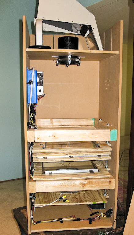
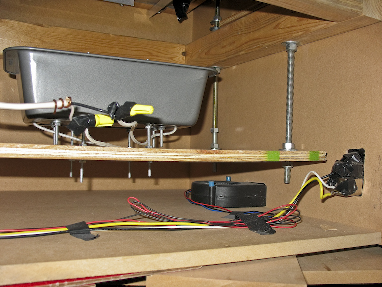
The gadget-porn view. The blue brick is the ballast for the 250W metal-halide light. Behind the blue brick is a computer power supply for the fan. I might use it to power the LCD controller too so the system will have a single power cord. The light is in the breadpan at the bottom, and the three wood plates hold the fresnell lenses and the LCD. |
 |
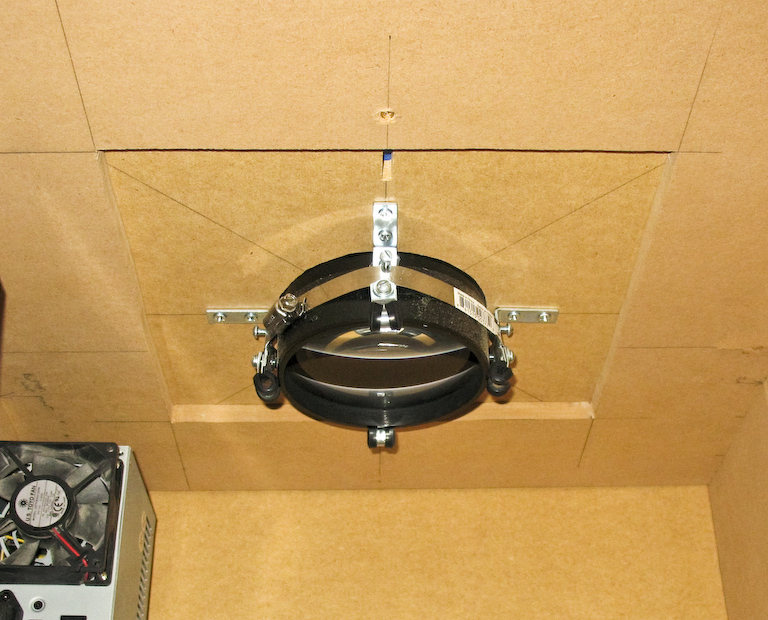
The 22in focal-length objective lens mounted up top. Four L-brackets with jb-welded nuts are stays for the side-screws. Each bracket is topped with an insulated conduit mount to provide a little overhang. The whole contraption is squished together with a hose-clamp. The 2-board design of the top lets me shift the lens side-to-side to minimize keystoning. |
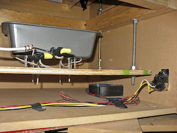 |
At the bottom, here's the mounted light, the squirrel cage fan, and the switched power plug that pokes out the back. |
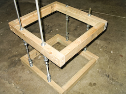 |
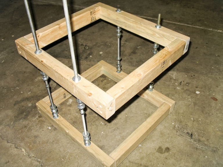
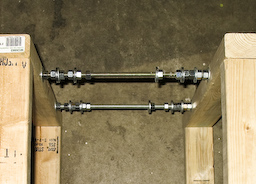
The frame that serves as the chassis for for the cabinet. Four 1/4in threaded rods, mounted with bolts and washers onto two frames of 2x3s. This was a test setup before I matched the length of all the rods. |
 |
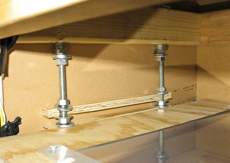
The adjustable mounting system of bolts and washers. Each wood plate rests between two washers. |
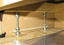 |
When you mount a plate between washers, the sides opposite the threaded rod needs some support, so I made a bunch of plywood inserts with arcs cut to fit the threaded rod. |
 |
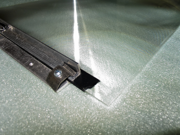
My first attempt at mounting the fresnell lenses used aluminum and springy clips on two edges of the lens. This only kept two sides rigid, and it was way too difficult to keep the lens from distorting. |
 |
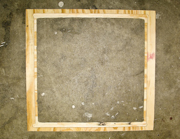
Wooden frames are now used as plates for each element. The springy clips and L-shaped aluminum now screw into the plywood plates, which provides rigid support. The shapes are actually flat, this picture just has a bunch of curvy distortion. |
 |
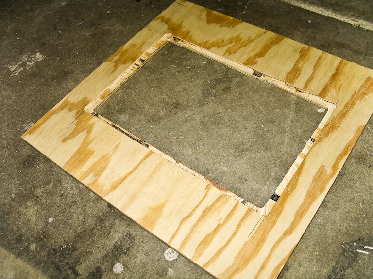
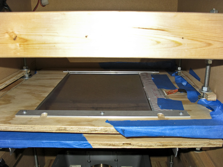
The plywood plate for the LCD. A square cutout with a lip routed into the edge (lined with foam insulator) holds the LCD. The height of the plate was made to fit between the threaded rods of the chassis. |
 |
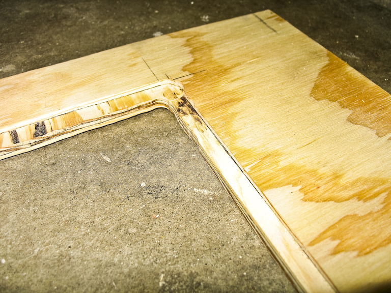
Close-up of the plate for the top fresnell. |
 |
And the plate for the bottom light-collecting fresnell. |
 |
The LCD is only restrained on two sides to keep from stressing the fragile wire connection. The L-shaped aluminum isn't needed since the LCD panel is fairly rigid itself. |
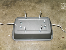 |
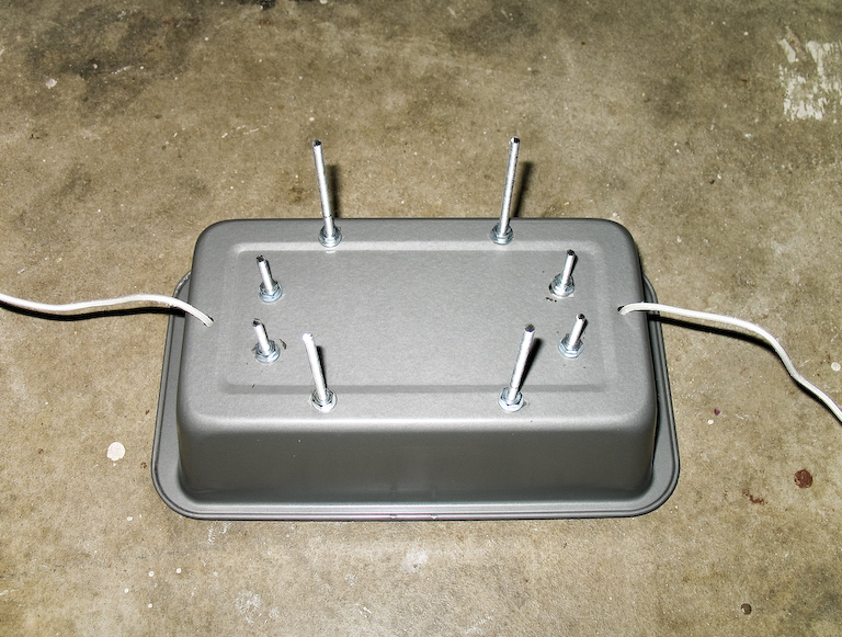
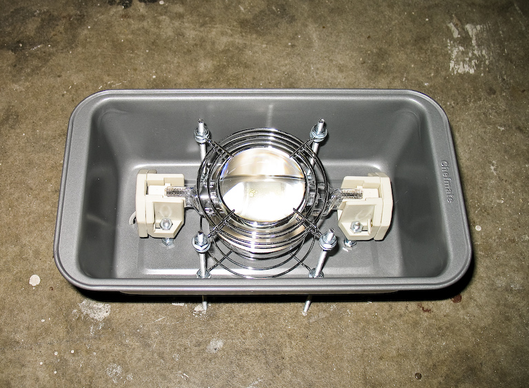
The light is mounted in the bread pan on #10 threaded rods. The pan shape is perfect for enclosing a light that only needs to shine one direction. |
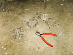 |
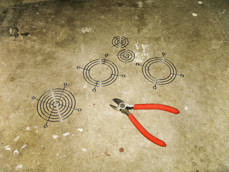
Wire PC fan grills with the centers removed. Two of these sandwich a condensor lens right in front of the light. It's very hot here, so you need materials that will last. |
 |
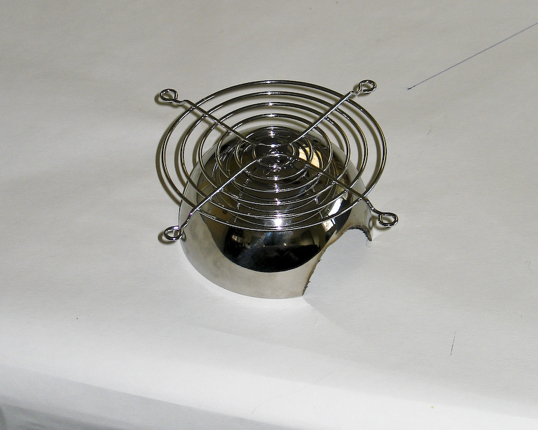
The reflector for the back of the light, jb-welded to ainother wire fan grill. I'll try out a different reflector if Lumenlab ever sends me the right part. |
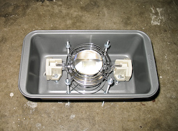 |
Front view of the light box. A 250W double-ended HQI metal-halide light, with connectors mounted to threaded rods. A ladle reflector underneath the light, and a condensor lens on top. |
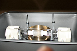 |
My condensor lens turned out to be the wrong focal length for my kind of setup, so now the light sits with just a reflector behind it. |